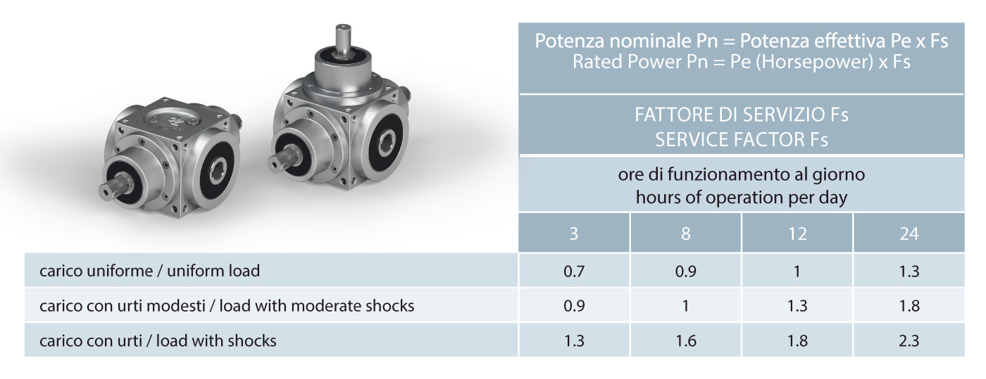
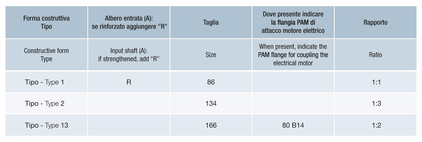
Determination of the right-angle gear
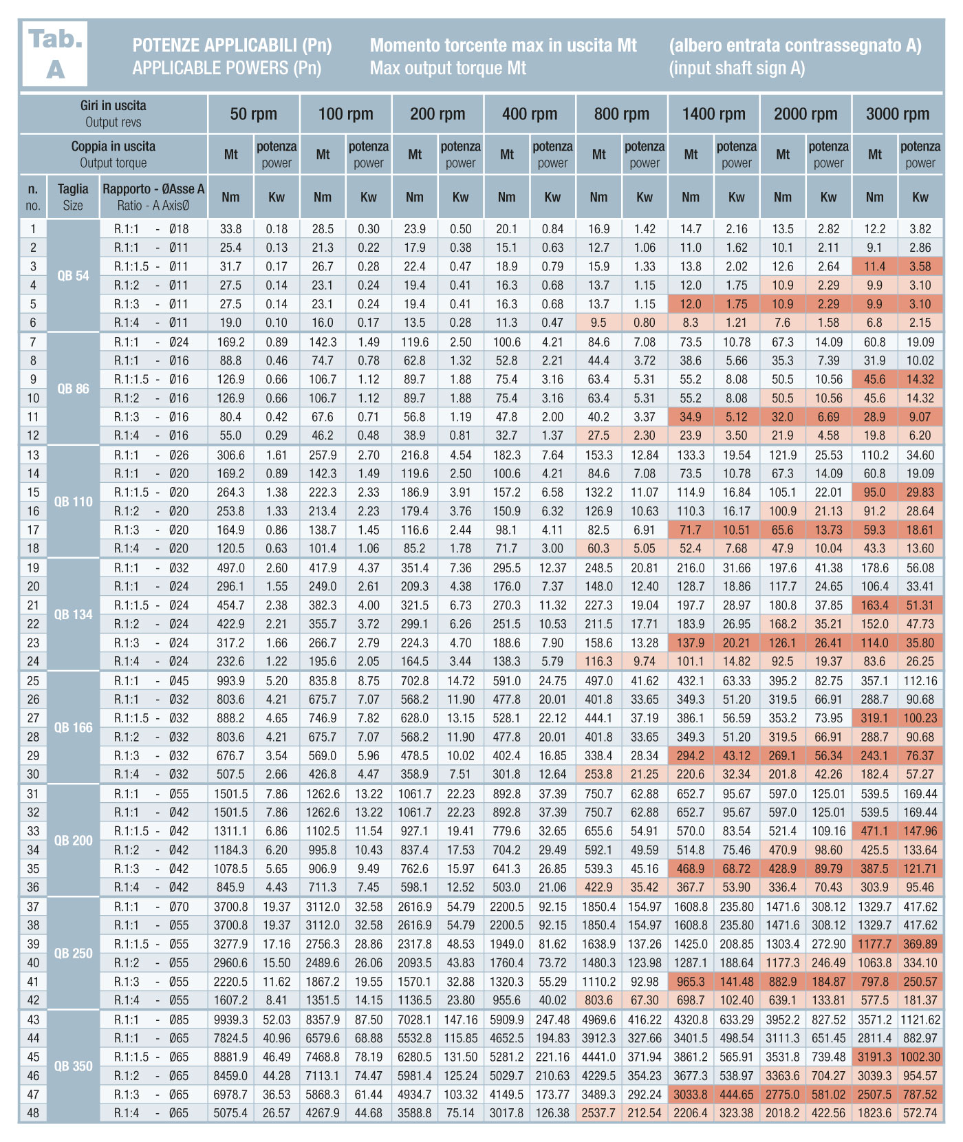
First of all, begin from the nominal value that the right-angle gear drive must ensure during its lifespan. The table A indicates the max powers (kW) and torques (Mt) recommended in relation to the number of rpms at which the load is applied. These values are considered with a safety factor that is never less than 3 for the right-angle gear drive’s weakest part, whether it refers to the bearings or gears or other drive gears such as splines or other. Everything is calculated for a minimum life of 5000 hours for parts subject to wear at a constant rotation speed of 1000 rpm on the slow axis. These parameters define what can be the rate of the right-angle gear drive inspections.
Consider that these rates are carried out with constant load conditions (Service Factor = 1) and with the maximum load allowed by the right-angle gear drive, with working conditions between -20° and +80° C. Under overload or low load conditions, the duration of the mechanical components does not have a linear proportionality. For example, it may last much less with an overload of 130 to 140% as compared to the nominal load. Likewise, if the load has a non-linear pattern the service factor will vary accordingly. On the contrary, a reduced load use of 80 to 90% lengthens the duration exponentially, especially the right-angle gear drive’s pitting.
The table summarizes how to locate the service factor based on the type of load applied and consequently by how much you can increase the heaviness of the load itself.
Table A and Table B show the 5 ratios available for each size.
There are two rows of values for all sizes in the 1:1 ratios.
This differentiation is due to the size of input shafts A or D which, even if “normal”, withstand less transmissible torque or power as compared to the R “reinforced” ones.
This distinction was not present in the previous versions but became essential after the new design with the use of larger bearings and gears that, size being the same, have enabled the transmissibility of greater torques and powers, compelling us to review the differences found between reinforced shafts/grooved profiles and small standard shafts, no longer sufficient to exploit the entire power increase of the new project.
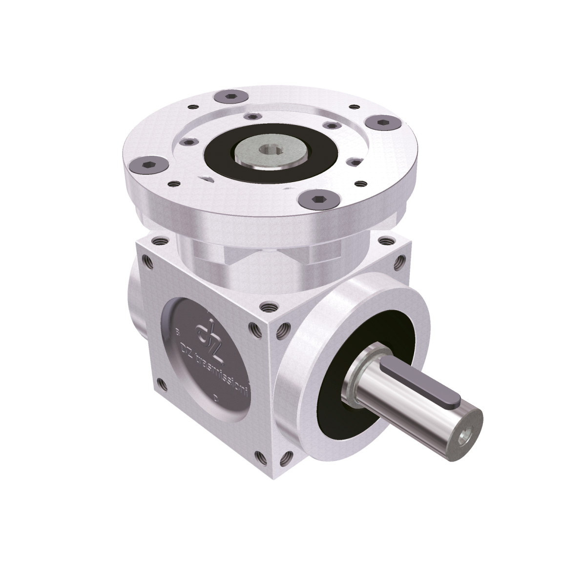
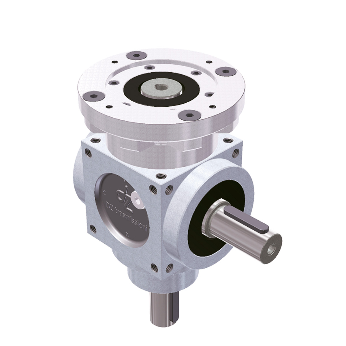
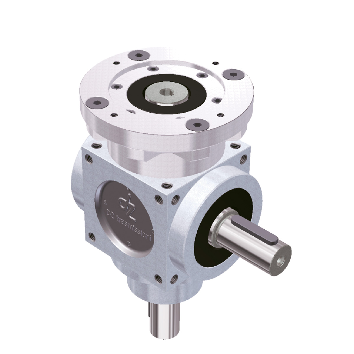
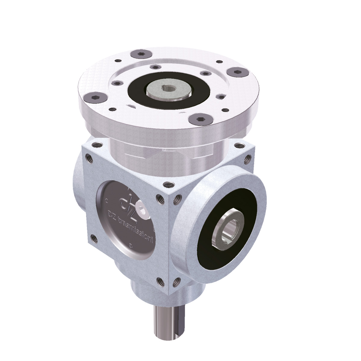
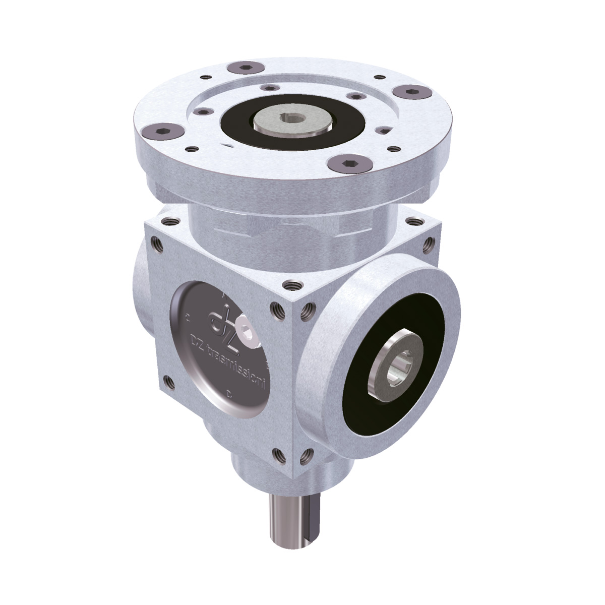
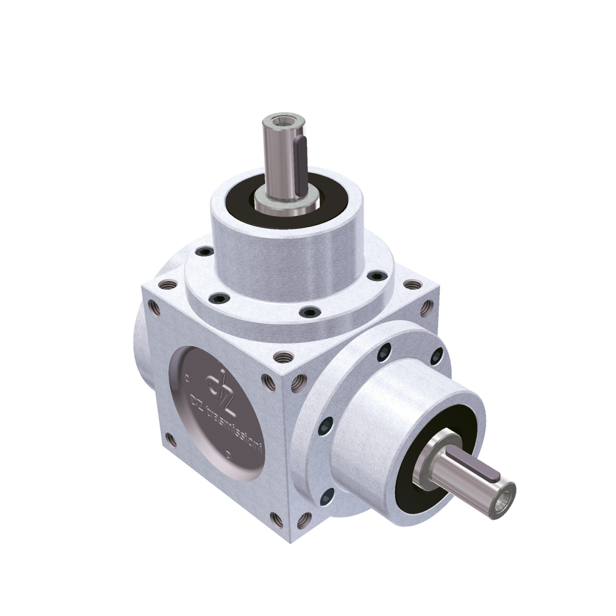
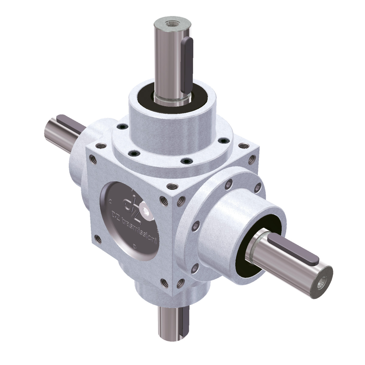
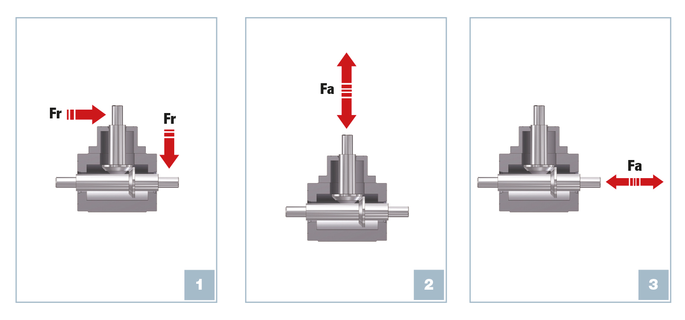
This type of load, that the right-angle gear drive will have to withstand, can result from certain components of the forces acting perpendicular to the right-angle gear drive’s axis by pushing or pulling the shaft.
The most common example is given by a belt’s tension load where a part of the radial force axially affects the shaft, which houses the pulley.
There may be several conditions involved in the creation of axial forces, even the gears that generate axial forces as they rotate, made with spiral toothing.
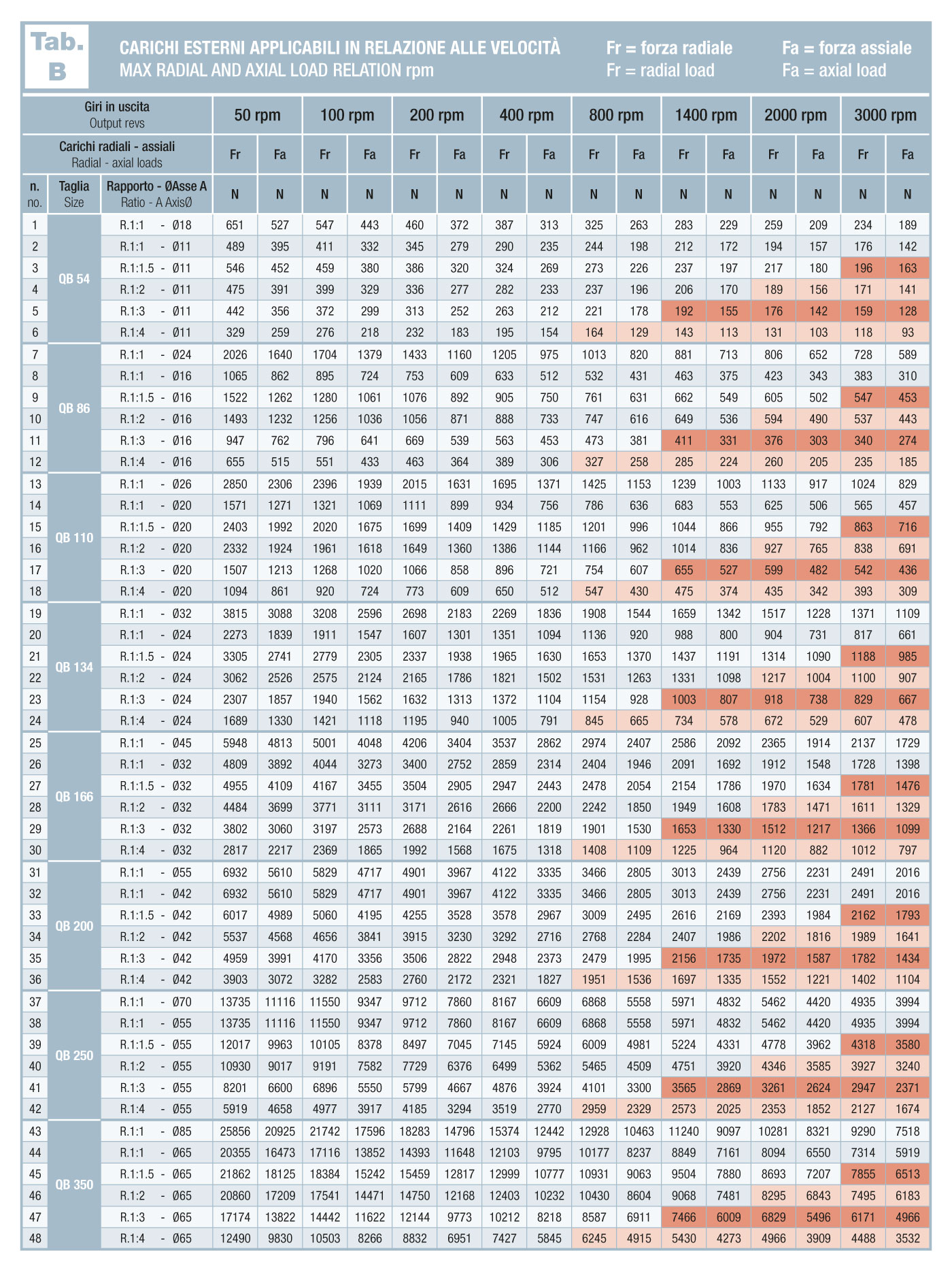
The conditions of maximum axial load that the various right-angle gear drives can withstand are summarized in the axial loads table.
This table shows, according to rotation speed, the radial force (example 1) and the axial force (examples 2 and 3) that the various right-angle gear drives can withstand, considering the radial load applied at a distance equal to half the protrusion of the shaft and, for hollow shafts, a maximum overhang of the point of application, the same as that of the respective model with the male shaft.
As in the previous cases, these are maximum recommended values.
The values in the tables A and tables B with the red color stand for limit or non-preferential conditions. Hence, if you have to work under these load and rpm conditions, contact our technical department for greater safety.

When operating bevel gears at low rotation rates ( < 100 rpm ), inadequate lubrication of the internal organs can occur and consequently the use of the following supplementary applications is required, depending on the chosen fitting position:
In cases of continuous operation and Service Factor FS=1 (see table) with rotation rates > 600/700 rpm the use of a bleeder vent is recommended to avoid the formation of high pressure and foam, while for rotation rates above 1400 rpm the use of an external cooling circuit is recommended.